![]()
FAQ Motorized Stage
- Connection / configuration example / Instruction Manual
- Dimensions / tolerances / drawings / material
- Mounting direction / load capacity / overhang
- Origin sensor / limit sensor
- Speed setting
- Cable-related / set model accessories
- Temperature / vacuum / use such as vibration environment
- Maintenance / grease / product life
- Custom order / remodeling / alteration
- Others : Cautions when using
- Repair
- Failure diagnosis
- Terms / definition (accuracy, unit, etc.)
Connection / configuration example / Instruction Manual
Minimum requirements for moving an motorized stage?
We are considering using an motorized stage.
What do we need besides the stage to actually move it?
◆ When using our recommended stepping motor controller (DS102 / 112)
[Operation with the handy terminal]
1) Motorized stage
2) Cable to connect between stage and controller
3) Handy terminal (DT100)
[Operation with PC]
1) Motorized stage
2) Cable to connect between stage and controller
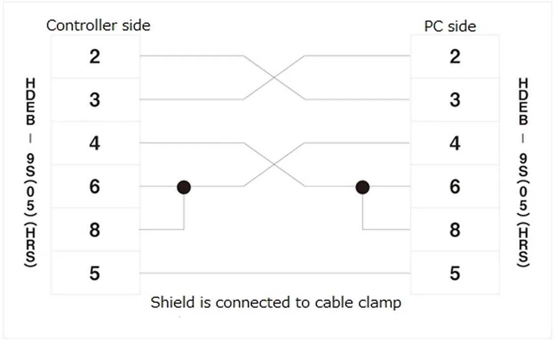
3) Cable to connect PC and controller (RS232C cable or USB cable)
* When using a publicly available product of RS232C : D100-R9-2,
USB : DS100-USB-1.8 RS232C cable,
it is necessary to check the connection (cross cable)
How to control an Motorized stage with 3 axes or more with Suruga Seiki controller (DS102 / DS112)
I'm thinking of purchasing Suruga Seiki controller (DS102 / DS112) and 4-axis of motorized stages.
How do I connect and use it? Do I need two controllers?
To control 4 axes, 2 of our controllers are required.
Connect the controllers with a dedicated link cable (model : DS100-LINK2-0.5).
Only one handy terminal is required, since commands to the controller are issued only to the controller set as the master unit.
Instruction manual of the controller and driver
I would like to know the detailed specifications of the controller (DS series) and other drivers sold by Suruga Seiki. Do you have any documents?
The instruction manual can be downloaded from the web site of Suruga Seiki.
Dimensions / tolerances / drawings / material
Position of the stage carriage in the drawings (center of the travel range)
As the installation space of the stage is limited, I am concerned about the maximum length of the stage with full stroke.
Is the position of the stage carriage in the drawings at the center of the travel range?
In principle, all the drawings of stages show when carriages are in the center of the travel ranges.
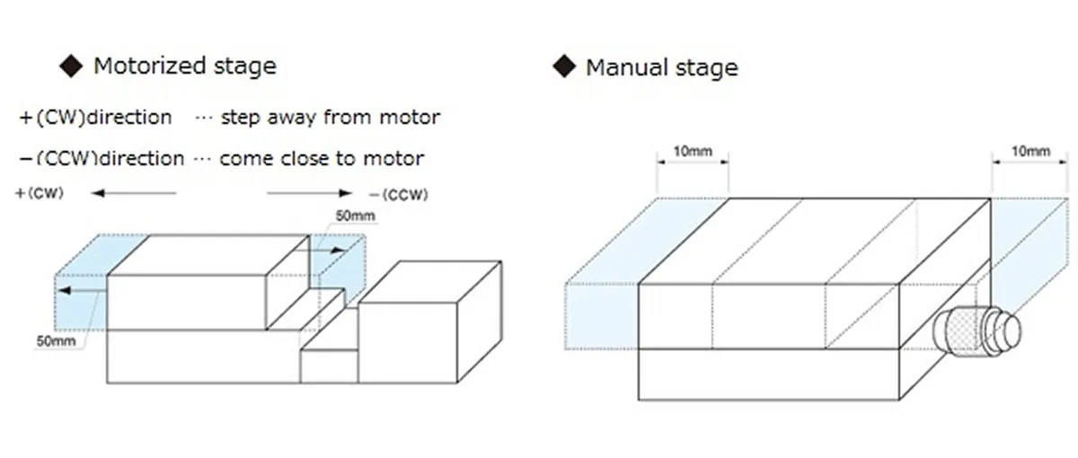
◆ Motorized Stage
The travel range represents the full travel length.
For example, in the case of 100 mm, centering on the position shown in the trace diagram,
the stage move 50mm in positive direction (CW) and 50mm in negative direction (CCW)
◆ Manual Stage
The travel range is indicated by +/- from the center. For example, in the case of +/-10mm,
centering on the position shown in the trace diagram, the stage move 10mm in negative direction and 10mm in positive direction(* full travel length is 20mm)
[exception]
There is an exception in manual Z-axis stages.
In that case, rather than showing travel range by +/- , it shows travel range in each of positive and negative directions.
[Stage height - dimensional tolerance] PG413 series
What is the height tolerance of the motorized X-axis stage (PG413 series/body part)?
It is equivalent to general dimension torelance midium grade, against the height of main body excluding motor (20mm).
KS451-40 φ8mm through hole
In the dimensional drawing of the KS 451-40, it is described as “transmission hole diameter φ8 (H7)” at the center of the stage carriage.
Is it good to recognize that this transmission hole is a φ8 mm transmission hole with the center of the stage carriage and the main body aligned?
Although it is described as φ8 mm, in fact, the diameter of stage carriage is φ8.2 and that of the main body section is φ8mm.
Also, the central axis of the transmission hole is not aligned with the transmission hole on the stage carriage.
Therefore, the diameter of the stage carriage is larger than the reference transmission hole.
Mounting direction / load capacity / overhang
Load capacity when mounted upside down
We are considering using various stages (X axis, horizontal Z axis, rotation, gonio) by attaching to the ceiling.
How much does the load capacity deteriorate compared to the load capacity (horizontal placement) described in the catalog?
The specifications of each product are based on the conditions when installed on a flat surface.
Because the load applied to the stage guide changes, it is not possible to clearly define the load capacity when mounting with upside down.
However, we are showing the following informaiton only for reference.
◆ Possible to use if the load point is directly below the stage carrier (center).
The load capacity shall be less than one third (1/3) of the horizontal load capacity.
* When load is applied to outside of the stage carriage, it is impossible to determine standard load capacity, and use is not recommended.
・X-axis stages
・Horitontal-plane Z-axis stages
・Goniometer stages
・Motorized rotary stages : KRW, KS402 Series
◆ Upside down use is not recommended
・Motorized rotary stage : KS451, KRE04360/06360 series, KS421 series (discontinued)
・Z-axis stage : KZS series
Load capacity when mounted vertically (Z-axis)
We are considering attaching various stages (X axis, horizontal plane Z axis, rotation, gonio) to the bracket so as to use vertically (side vertical use).
How much does the load capacity deteriorate compared to the load capacity (horizontal placement) described in the catalog?
■ X-axis stages:
If there is a model of Z-axis stage with bracket attached to the stage, please refer to the load capacity of that stage . (Example : PG413M-LA-C → PZG413M-LA-C)
■ Other products:
The specifications of each product are based on the conditions when installed on a flat surface.
Because the load applied to the stage guide changes, it is not possible to clearly define the load capacity when mounting with upside down.
However, we are showing the following informaiton only for reference.
◆ Possible to use if the load point is directly below the stage carrier (center).
The load capacity shall be less than one third (1/3) of the horizontal load capacity.
* When load is applied to outside of the stage carriage, it is impossible to determine standard load capacity, and use is not recommended.
・Horitontal-plane Z-axis stages (connector to be in up and down directioni)
・Goniometer stages
・Motorized rotary stages : KRW, KS402 Series
◆ Side vertical use is not recommended
・ Motorized rotary stage : KS451, KRE04360/06360 series, KS421 series (discontinued)
Load capacity when mounted on a wall moving horizontally
We are considering using various stages (X axis, horizontal plane Z axis, rotation, gonio) attached to the bracket so that the moving direction of the stage is horizontal (side horizontal use).
How much does the load capacity deteriorate compared to the load capacity (horizontal placement) described in the catalog?
The specifications of each product are based on the conditions when installed on a flat surface.
Because the load applied to the stage guide changes, it is not possible to clearly define the load capacity when mounting with upside down.
However, we are showing the following informaiton only for reference.
◆ Possible to use if the load point is directly below the stage carrier (center).
The load capacity shall be less than one third (1/3) of the horizontal load capacity.
* When load is applied to outside of the stage carriage, it is impossible to determine standard load capacity,and use is not recommended.
・X-axis stages
・Horitontal-plane Z-axis stages (connector to be left-right position mounted on wall)
・Goniometer stages
・Motorized rotary stages : KRW, KS402 Series
◆ Possible to use if the load point is directly below the stage carrier (center).
The load capacity shall be less than one third (1/3) of the horizontal load capacity.
* When load is applied to outside of the stage carriage, it is impossible to determine standard load capacity, and use is not recommended.
・Horitontal-plane Z-axis stages (connector to be in up and down directioni)
・Goniometer stages
・Motorized rotary stages : KRW, KS402 Series
◆ Side vertical use is not recommended
・ Motorized rotary stage : KS451, KRE04360/06360 series, KS421 series (discontinued)
KRE 04360 · 06360 in vertical direction
I would like to use the motorized rotation stage KRE04360 / 06360 vertically (side horizontal, side vertical) .
The KRE series can not be structually used in vertical direction or or in the condition that overhang load is applied from the stage carriage.
For vertical use, please select the KRW · KS402 series.
* Please handle with load capacity 1/3 or less of specifications also in that case.
Origin sensor / limit sensor
How to change the limit sensor position of KS402 series
The motorized rotary stage "KS402-75" is described in the catalog that the position of the shielding plate for the limit sensor can be changed. Please tell me how to adjust it.
There are clamps with M3 bolt for shielding plate on the stage carriage.
In the catalog drawing, it is close to the limit sensor switch box.
When the clamp is loosened, the protruding parts around stage carriage become movable.
When these protrusion parts are moved, the shielding plate can be adjusted.
Once the position of shielding plate is determined at any angle, tighten the clamp of the shielding plate on the stage carriage.
* Please apply the following torque for tightning the set bolt: KS402-75 : 5cN・m、KS402-100 : 25cN・m
Origin return for 2 sensor stages with D70 controller
I have a controller (model : D70) that was sold by Suruga Seiki in the past.
As I have a motorized stage with 2 sensors (limit sensors only) and a cable to connect to the controller,
I tried to use the D70 controller, but origin return did not work.
The D70 can not perform origin return on a 2-sensor motorized stage.
When D70 controller was sold, we were not selling motorized stages without origin sensor.
Therefore, it does not support origin return operation for motorized stage with limit sensors only (without origin sensor).
■ 2-sensor stages
· KXL series (when origin sensor option is not selected)
· KRB series (The current products KRB04017C and KRB06011C have 3 sensor specifications.)
What is the slit origin sensor (ORG2, ORG)?
What is the slit origin sensor (ORG2 / ORG)?
The D70 can not perform origin return on a 2-sensor motorized stage.
The slit origin sensor (ORG2 / ORG) is a type of origin sensor that mounts a disk with slits on the rotating shaft of the motor and detects the position of the slits with a photomicro sensor.
After detecting the origin sensor (ORG1 / NORG) of the stage main body, origin return is performed based on the step angle of the motor.
* Some products have only CW / CCW limit sensor depending on the model.
In that case, origin return is performed based on the limit sensor.
* Except for the KXS & KS102 series, the slit origin sensor can not be used with the standard cable supplied with the motorized stage.
A separate dedicated cable is required (D214-2- ● EA (K), D214-2- ● RA (K)).
Speed setting
Setting of acceleration / deceleration time (indication to avoid step out)
[Acceleration / deceleration] Is there a setting that does not cause a step out?
There is no clear specification because it varies depending on conditions such as workpiece weight and shape, center of gravity position, ball screw lead and so on.
The adjustment will be made with about 100 msec to 200 msec as a reference.
Slowing the stage moving speed as much as possible
I want to slow down the speed of the stage as much as possible.
It is possible by reducing the pulse volume from the controller.
However, as vibration is likely to occur if the speed is slow, please consider increasing the number of divisions with MS (micro step) if you want to drive the stage smoothly.
Can I speed up the MAX speed if the workpiece is light?
A 1 kg workpiece is mounted on a product with a 10 kg load capacity. Can MAX speeds be faster than catalog guaranteed values?
The catalog warranty value does not change even if certain conditions are relaxed.
Please use within the catalog guarantee value.
Does MAX speed get slower if resolution is finer?
Does the finer resolution lead to a slower MAX speed?
Even if the resolution becomes finer, the speed will not change as more pulses are sent to the driver.
However, since there is a pulse setting range of the controller, use it within that range.
How to calculate the acceleration
I purchased a motorized X axis stage.
Please tell me the acceleration when moving at MAX speed.
Acceleration a represents the change in velocity per unit of time. It can be expressed using the following formula:
a = Δv / Δt = ( Max Speed - Initial Speed ) / Acceleration/Deceleration Time
Calculation Example 1
Below is a calculation example for a drive operation under the following conditions:
・Initial Speed: 1 mm/sec
・Max Speed: 10 mm/sec
・Accel/Decel Time: 0.1 sec
In this case, the acceleration $a$ is calculated as follows:
a = ( 10 [mm/sec] - 1 [mm/sec] ) / 0.1 [sec] = 90 [mm/sec^2] = 0.09 [m/sec^2]
Calculation Example 2
The following is a calculation example when using our DS102 Controller with Speed Table No. 7 to drive a stage with a resolution of 2 μm/pulse.
The units have been standardized to match Example 1.
Specifications for Speed Table No. 7:
・Starting Speed: 1000 pps ⇒ 1000 pulses/sec × 2 μm/pulse = 2000 μm/sec = 2 mm/sec
・Driving Speed: 10000 pps ⇒ 10000 pulses/sec × 2 μm/pulse = 20000 μm/sec = 20 mm/sec
・Accel/Decel Time: 100 msec ⇒ 0.1 sec
*Note: [pps] stands for pulses per second, indicating the number of pulses per second.
In this case, the acceleration $a$ is calculated as follows:
a = ( 20 [mm/sec] - 2 [mm/sec] ) / 0.1 [sec] = 180 [mm/sec^2] = 0.18 [m/sec^2]
Cable-related / set model accessories
Items included in the motor option with an electromagnetic brake
What is included when selecting the electromagnetic brake motor option (MA/MB/SA)?
*Note: Option SA is available for the KXS Series only.
The included accessories vary depending on the cable option selection code.
The details are as follows:
◆CAVE-X series (KXG/KXL series)
1) Driver (Manufactured by Oriental Motor)
・ None / 3 / 5: Not included
・ 3A / 5A: (MA) RKSD503M-A / (MB) RKSD503M-C
2) Cable Set for Electromagnetic Brakes (Common to MA/MB, Oriental Motor)
・ None / 3 / 5: Not included
・ 3A: CC030VPFB (3m / For fixed)
・ 5A: CC050VPFB (5m / For fixed)
3) Sensor Cable (Common to MA/MB)
・ None: HR10AP-S-SB-6-2 (2m / For fixed)
・ 3 / 3A: HR10AP-S-SB-6-3 (3m / For fixed)
・ 5 / 5A: HR10AP-S-SB-6-5 (5m / For fixed)
◆PG series
1) Driver (Manufactured by Oriental Motor)
・ None / 3 / 5: Not included
・ 3A / 5A: (MA) RKSD503M-A / (MB) RKSD503M-C
2) Cable Set for Electromagnetic Brakes (Common to MA/MB, Oriental Motor)
・ None / 3 / 5: Not included
・ 3A: CC030VPFB (3m / For fixed)
・ 5A: CC050VPFB (5m / For fixed)
3) Sensor Cable (Common to MA/MB)
・ None: PG-H-ASSY5-2000 (2m / For fixed)
・ 3/3A : PG-H-ASSY5-3000 (3m / For fixed)
・ 5/5A : PG-H-ASSY5-5000 (5m / For fixed)
◆ Slide Guide (KXS) Series
When the electromagnetic brake motor option is selected for the KXS Series, only the following accessory set is included.
・Driver : RKSD507M-A (Oriental Motor Co., Ltd.)
・Electromagnetic Brake Cable (3 m) / motor cable (3 m) set : CC030 VPFB (made by Oriental Motor)
・sensor cable (2 m) : D214-1-2EK
* The above cable is a fixed cable.
Items included in the Motor option: αSTEP
What is included when selecting the Motor option: α STEP (PA/ZA/QA)?
*Note: Option QA is available for the KXS Series only.
The included accessories vary depending on the cable option selection code.
The details are as follows:
◆CAVE-X series (KXG/KXL sereis)
1) Driver(Manufactured by Oriental Motor)
・ None / 3 / 5: Not included
・ 3A/5A: (ZA) AZD-K / (PA) ARD-K
2) MotorCable (Manufactured by Oriental Motor)
・ None / 3/ 5: Not included
・ 3A: (ZA) CC030VZ2R2 / (PA) CC030VA2R2 (common: 3m/for flex)
・ 5A: (ZA) CC050VZ2R2 / (PA) CC050VA2R2 (common: 5m/for flex)
3) SensorCable (common to ZA/PA)
・ None: HR10AP-S-SB-6-2 (2m/for fixed)
・ 3/3A : HR10AP-S-SB-6-3 (3m/for fixed)
・ 5/5A : HR10AP-S-SB-6-5 (5m/for fixed)
◆PG series
1) Driver(Manufactured by Oriental Motor)
・ None / 3 / 5: Not included
・ 3A/5A: (ZA) AZD-K / (PA) ARD-K
2) MotorCable (Manufactured by Oriental Motor)
・ None / 3/ 5: Not included
・ 3A: (ZA) CC030VZ2R2 / (PA) CC030VA2R2 (common: 3m/for flex)
・ 5A: (ZA) CC050VZ2R2 / (PA) CC050VA2R2 (common: 5m/for flex)
3) SensorCable (common to ZA/PA)
・ None: PG-H-ASSY5-2000 (2m/for fixed)
・ 3/3A : PG-H-ASSY5-3000 (3m/for fixed)
・ 5/5A : PG-H-ASSY5-5000 (5m/for fixed)
◆ Slide Guide (KXS) Series
When the αSTEP motor option is selected for the KXS Series, only the following accessory set is included.
・Driver : ARD-A (Oriental Motor Co., Ltd.)
・Motor cable (3 m) : CC030VAR (movable cable)
・Sensor cable (2 m) : D214-1-2 EK (fixed cable)
Items included in servo motor option
What is included when the Mitsubishi Electric J4 Series is selected as the servo motor option (UA/WA)?
*Note: Option WA is available for the KXS Series only.
The included accessories vary depending on the cable option selection code.
The details are as follows:
◆CAVE-X series (KXG/KXL series)
1) Amplifier
・ None / 3 /5: Not Included
・ 3A / 5A: MR-J4-10A
2) Motor Cable
・ None / 3 /5: Not Included
・ 3A: SVPM-J3HF1-B-3-02S (3m/for flex)
・ 5A: SVPM-J3HF1-B-5-02S (5m/for flex)
3) Encoder Cable
・ None / 3 /5: Not Included
・ 3A: SVEM-J3HF1-B-3 (3m/for flex)
・ 5A: SVEM-J3HF1-B-5 (5m/for flex)
4) Sensor Cable
・ None: HR10AP-S-SB-6-2 (2m/for fixed)
・ 3/3A : HR10AP-S-SB-6-3 (3m/for fixed)
・ 5/5A : HR10AP-S-SB-6-5 (5m/for fixed)
◆PG series
1) Amplifer
・ None / 3 / 5: Not Included
・ 3A / 5A: MR-J4-10A
2) Motor Cable
・ None / 3 / 5: Not Included
・ 3A: SVPM-J3HF1-B-3-02S (3m/for flex)
・ 5A: SVPM-J3HF1-B-5-02S (5m/for flex)
3) Encoder Cable
・ None / 3 / 5: Not Included
・ 3A: SVEM-J3HF1-B-3 (3m/for flex)
・ 5A: SVEM-J3HF1-B-5 (5m/for flex)
4) Sensor Cable
・ None: PG-H-ASSY5-2000 (2m/for fixed)
・ 3/3A : PG-H-ASSY5-3000 (3m/for fixed)
・ 5/5A : PG-H-ASSY5-5000 (5m/for fixed)
◆ Slide guide (KXS) serie
When the servo motor option is selected for the KXS Series, only the following accessory set is included.
・Amplifier:MR-J4-10A (made by Mitsubishi Electric Corporation)
・Motor cable (3 m):SVPM-J3HF1-B-3-02S (movable cable)
・Encoder cable (3 m ):SVEM-J3HF1-B-3 (movable cable)
・Sensor cable (2 m):D214-1-2 EK (fixed cable)
I want to know information such as thickness and bending radius of attached cable
Please tell me the thickness and minimum bending radius of the attached cable (model : D214-2-2RK).
◆ Robot cable
finish Outline : 6.70 ± 0.15 mm
(Conductor configuration : 50 pieces / 0.08 mm [24 AWG], conductor outer diameter : approx. 0.65 mm)
Minimum bending radius : R33 mm
Normal cables are as follows.
◆ Normal cable
finish Outline : 6.70 ± 0.15 mm
(Conductor configuration : 40 pieces / 0.08 mm [24 AWG], conductor outer diameter : approx. 0.65 mm)
Minimum bending radius : R33 mm
What is the cable set for DC24V input driver used for?
What is the following cable set used for?
◆ Product name : Cable set for DC24V input driver
◆ Model : LCS04SD5
In order to connect each stage to the driver, it is necessary to crimp using the special tool for the attached connector, but if you use this Cable set for DC24V input driver, you can omit the crimping operation.
Following 3 cables with connectors all 600mm) are included in the Cable set for DC24V input driver
1) Driver and DC power supply
2) Driver and motor
3) Driver and host controller
The other side of cables are left without connectors, so please connect them using a terminal block etc.
Cable connection diagram shows sensor as DC5V
Looking at the cable (D214) connection diagram, the sensor power supply is 5 VDC,
but can it be used at 24 V?
There is no problem with use at 24V. The same cable is used for both sensor power supply 5V / 24V.
Is the cable extending from the main unit robot cable?
Is the cable extending from the body of the motorized stage a fixed cable?
Or is it a movable cable (robot cable)?
It is a fixed cable.
When mounting in a place where the motorized stage itself moves, fix the connector so that the cable does not bend or twist.
Cable connecting driver and host
We are considering to use 5-phase stepping motor driver CRD5107P or CVD507-K-A9.
How should I select the wiring cable when connecting to the control board or power supply?
■ Power Cable
Please use a power cable AWG22 (0.3mm ^ 2) cable.
■ I/O Cable
Please use the cable of I / O cable AWG24 (0.2mm ^ 2)-AWG22 (0.3mm ^ 2).
A dedicated crimping tool is required to assemble and wire the connector that comes with the DC24V Type Input Driver.
There is a product with 600 mm cable crimped to the connector attached to the driver.
Model : LCS04SD5 (Cable set for DC24V input driver)
A set of three for driver and DC power supply, driver and motor, and driver and host controller.
As we can just plug in driver, we can use immediately.
There is no need for laborious connector and wire crimping work, no special crimping tool,
and driver damage due to incorrect wiring can be prevented.
* The other side of the driver is processed with loose wires.
* A dedicated crimping tool is required to assemble and wire the connector included with the DC24V driver.
Temperature / vacuum / use such as vibration environment
Usable temperature range
Is there a temperature range that can use the stage?
The use environment of the stage is as follows.
Operating environment : 10 to 50 ° C, 20 to 70% RH (non-condensing)
Recommended operating environment : 22 ± 5 ° C, 20 to 70% RH (non-condensing)
Use in environments other than the recommended operating environment (22 ± 5 degrees)
Can you use it other than the recommended usage environment (22 ± 5 degrees)?
It is possible to use.
However, thermal expansion and contraction occur in the temperature change.
It is recommended to use at a constant temperature if it is used for precise measurement.
If the temperature change is large, let the stage adapt to that temperature for several hours before using.
The use environment of the stage is as follows.
Operating environment : 10 to 50 ° C, 20 to 70% RH (non-condensing)
Recommended operating environment : 22 ± 5 ° C, 20 to 70% RH (non-condensing)
Availability in environments with severe temperature changes
Can you use it in the environment with temperature change?
It is possible to use.
However, thermal expansion and contraction occur in the temperature change.
It is recommended to use at a constant temperature if it is used for precise measurement.
If the temperature change is large, let the stage adapt to that temperature for several hours before using.
* We do not measure data for temperature change.
The use environment of the stage is as follows.
Operating environment : 10 to 50 ° C, 20 to 70% RH (non-condensing)
Recommended operating environment : 22 ± 5 ° C, 20 to 70% RH (non-condensing)
Unusable Environment (Unusable)
Is there an environment where you can not use the stage?
Please avoid using in the following places.
・A place with a lot of dust and dust (especially metal powder)
・A place exposed to direct sunlight and radiant heat
・A place close to fire
・A place where a corrosive gas or flammable gas is generated
・A place with water or oil
・A place where vibration or shock is transmitted
・A place with lots of salt and organic solvents
Is there a vacuum compatible stage?
Is there a vacuum compatible stage?
There is no vacuum compatible stage.
However, we provide grease replacement with Solva Specialty Polymers Japan Inc.,
Grease for vacuum, Fomblin YVAC2
You can order with the option code by adding "-L" at the end of the model number.
■ Not applicable products:
Motorized goniometer stages, Morotized rotary stages, and Motorized horizontal Z-axis stages are not compatible with grease replacement.
Can I use it in a clean room?
Is it possible to use it in a clean room?
Our stages are not for clean environment.
However, we provide grease replacement (1:THK company-Clean environment grease-AFF / 2:NSK company-Clean environment grease-LG2).
You can order with the option code by adding "-J" or "-K" at the end of the model number.
▼ CAVE-X (Linear Ball Guide) series and KXS (Slide Guide) series
Except for bearing part, clean environment grease (AFF) is used as standard.
■ Not applicable products:
Motorized goniometer stages, Motorized rotary stages, and Motorized horizontal Z-axis stages are not compatible with grease replacement.
Availability in a humid environment
I want to use the stage in high humidity (70 to 90% etc.) to do environmental test.
Is it possible to use it?
When used at high humidity, rust may occur in the guide part.
Therefore, we do not recommend such use.
Maintenance / grease / product life
Products that can not be changed to clean grease (AFF)
If "-J" is added to the end of the model, you can select the option for clean environment grease (THK AFF Grease).
Are there any products that are not compatible?
Grease replacement for the motorized goniometer stages, the motorized rotary stages and the motorized horizontal Z-axis stage are not possible to order with the end code.
CAVE-X (Linear Ball Guide) series ,KXT series and Slide guide series use AFF grease as standard grease,
so "-J" option code at the end is unnecessary.
Stage product life
Is there a product life of the stage? Please tell me how long they can perform without accuracy/precision deterioration.
There is no provision for product life.
The actual usable period is difficult to estimate because it varies depending on the operating environment (temperature, humidity, etc.), how the load is applied, and the frequency of use.
Grease-up frequency
Are there any regulations or recommendations for the frequency of grease up?
There are no regular standards, regardless of the type of grease.
Depending on the driving conditions and guide type, check the grease condition about once a month and apply it as needed.
Grease-up method
Please tell me how to grease up.
1) Remove old grease within visible range.
2) Apply to a syringe etc.
3) Make the full stroke operation several times.
4) Wipe out any excess grease.
[PG Series] Grease for Guide
Please tell me the grease used in the guide of PG series.
Manufacturer name : Shell Lubricants Japan
Product name : Alvania Grease
Type : S2
* Please note that there is a possibility of changing without notice for product improvement.
[CAVE-X (Cayvex) Series] Grease for Guide
Please tell me the grease used in the CAVE-X series guide.
Manufacturer name : THK
Product name : Grease for clean environment
Model : AFF
* Guides and ball screw parts are common
* There is a possibility to change without notice for product improvement, so please be aware
[KXT series] Grease for guide part
Please tell me the grease used for the KXT series guide and ball screw.
Manufacturer name : THK
Product name : Grease for clean environment
Model : AFF
* Guides and ball screw parts are common
* There is a possibility to change without notice for product improvement, so please be aware
[Motorized cross roller stage] Grease on guide part
Please tell me the grease used for the guide part of the cross roller stage (linear motion / XY stage).
■ Guide
manufacturer name : Shell Lubricants Japan
Product name : Alvania Grease
Type : S2
■ Ball Screw
Manufacturer Name : Kyodo
Yushi Product Name : Martemp PS
Type : No. 2
* Please note that there is a possibility of changing without notice for product improvement.
[Motorized goniometer stage] worm gear portion of the grease
Please tell me the grease used in the worm gear of the gonio stage.
■ guide
Studio Name : Shell Lubricants Japan
Product Name : Alvania grease
Model : S2
■ worm gear
Studio Name : Shell Lubricants Japan
Product Name : Alvania grease
Model : HDX
* There is a possibility to change without notice for product improvement so please be advised
Custom order / remodeling / alteration
I want to assembled to the XY and Shifts from the center position
We are considering using KXL06300M-N2-FB assembled in XY.
Instead of being assembled at the center as in standard XY product like KYL 06300, we would like to make it a shifted position (the center of the upper axis is overhung with respect to the lower axis).
Are there any problems in use?
As it is a product with a 300 mm stroke, displacement (deflection) may occur when the upper shaft moves.
We recommend using the support guide if you want to stabilize the accuracy.
Model : APW 6016A -390A
* Please note that the stage with a cover is different from the model with APW 6019A -390A.
Custom handling of alteration work (such as tap holes)
Is it possible to add alternation work (such as tap holes) to the stage?
Depending on the content, it will be considered as a custom order.
Please contact our sales office for details.
Change to specified motor
Is it possible to replace the motor with other servomotor specified by us?
Depending on the content, it will be considered as a custom order. Please contact our sales office for details.
About XY combination of PG430 / PG530 / PG650 / PG750
I have multiple PG430 (530 · 650 · 750) X-axis stages. By combining two of them, will it become PMG430 (530 · 650 · 750) XY-axis stage?
If the 30 mm and 50 mm strokes of the PG series are assembled on XY as they are, they will interfere.
* The PMG430 / 530/650/750 series avoids interference through the intermediate plate.
Also, since the XY axis is a combination of L and R, the combination of L and R of PG does not have the same configuration as PMG.
Others : Cautions when using
Loaner of demo machine (sample product)
I am considering purchasing an automatic stage.
I would like to borrow a demo machine (sample machine) in advance and perform verification.
Is this possible?
Yes, it is possible.
Please contact our sales office with your desired product model, quantity, usage period and delivery address.
* Please note that we might not be able to prepare depending on the type and quantity.
No bracket for Z-axis stage
Although we are considering using the motorized stage in the Z-axis direction (vertical use),
the bracket is not necessary because it is attached directly to the wall.
Is it possible to purchase the Z axis stage without built-in bracket?
The configuration of the Z axis stage is "X axis stage + Z axis bracket".
Therefore, each stage can be purchased separately as an X-axis stage.
Example. KZL06030M-N1-C → "X-axis stage : KXL06030M-N1-C" + "Z-axis bracket : AZTW60A-140"
Role of knob (turn) attached to motor
There is a black knob (turn) on the motor of the motorized stage. What is this for?
The knob is used to move the stage manually when the power is off.
Depending on the product, when installing the motorized stage, it is necessary to turn the knob when the power is off and move the top plate until the bottom plate mounting holes come out.
I want to use an motorized stage as a power source
Can you use an motorized stage as a power source?
Our motorized stage is for precise positioning of objects placed on a table.
It cannot be used for applications as a power source because there is a risk of deterioration of life, accuracy, failure or damage.
Repair
Repair service at the time of failure or damage
It seems that a dent is caused in the guide when I dropped the stage.
I would like to request a repair. What should I do?
We will accept the actual machine if there is no problem other than the guide, then we will make a judgment on repair availability and present a repair estimate.
After receiving a repair instruction (ordering), we will start the repair work.
We will notify you of the symptoms, the shipping address, and the management number.
when sending out, so please contact our sales office for details.
Is there a charge for making a repair cost estimate (repair estimate)?
I would like to decide whether to repair after looking at the estimated price for repair.
Will there be any charge to get a quote after sending the actual machine?
As a rule, no expenses will be incurred.
If the need for additional work is found during repair work
The repair quote states that additional work may occur after the start of work. In that case, what happens to the amount?
In some cases, it may become clear that additional work is necessary during replacement / adjustment work.
In that case, we will inform you of the amount of change and the number of work days, and we will start work after accepting the start of additional work.
Failure diagnosis
Straightness is greater than catalog value (with rattling)
The motorized X-axis stage (PG413T-LA-C) is used to adjust the position of the camera.
I'm adjusting it while looking at the image, but I feel that it has a large rattle.
Mounting an object with a rough surface or attaching it to a surface with a rough surface may deform the stage surface and affect the accuracy. (The standard of flatness is within 10μm.)
Please check the flatness of the object and the mounting location.
Motor is out of step
We are using a motorized X-axis stage (PG413T-LA-C).
The stage is out of step though it is used within the catalog specs (MAX speed, load capacity).
What factors are considered?
A step out occurs when the motor is overloaded.
There are various concrete factors, but the following factors can be considered.
1) Acceleration speed is too fast
→ Make the acceleration / deceleration setting slower.
2) The operating temperature is low and the grease is hardening
→ Please warm up until the device temperature stabilizes.
3) Moment load is applied too much.
→ Make sure that the load is as close to the center of the top of the stage as possible.
[Motorized Rotary Stage (KRE)]
connected to the controller (DS102 / DS112 Series) but this stage does not move
I tried to use the motorized rotary stage (KRE04360, KRE06360) connected to the controller
I had before (DS102ANR), but it did not move.
Could you confirm the logic setting of the limit sensor?
Could you confirm the type of limit sensor logic as A (normally open) again on the parameter setting screen?
* There is no problem with the origin sensor logic as B (normally closed).
An error occurs during origin return
When attempting origin return of the motorized stage, the expected operation cannot be performed.
If you are using the DS102/112 series controller, please check if the origin return type matches with the stage series.
If the acceleration / deceleration rate is too long or the startup speed is too high, it cannot bestopped in time after limit detection, and may interfere with the mechanical limit or shift the origin return position.
The origin return position of the rotary stage does not match the marking line of the main body
Even if the origin return function is executed with recommended origin return type of the motorized rotary stage, the marking lines on the stage main body are not aligned.
The origin return position differs by origin return type for the width of dog, as each origin return type has difference pattern as to which side of the CW / CCW edge of the sensor signal is detected.
Please insert an offset function after origin return function on the software, or select the origin return type which can detect in the opposite direction.
The origin position deviates when the origin return type is changed (DS102 / DS112)
When the origin return type was changed in DS102 · 112, the origin position shifted.
The origin return position differs by origin return type for the width of dog, as each origin return type has difference pattern as to which side of the CW / CCW edge of the sensor signal is detected.
Please insert an offset function after origin return function on the software, or select the origin return type which can detect in the opposite direction.
Terms / definition (accuracy, unit, etc.)
Speed setting defined by "pps" (pulse per second)
I am trying to connect KXL06150M-N2-FA to DS102ANR. I want to set the maximum speed at 25 mm/sec.
I read the instruction manual, but the speed setting is written in pps and I do not understand it well.
How should I calculate?
The answer is based on the assumption that the controller division number setting is FULL step (*).
pps means pulse / sec (read as pulse per sec).
The speed unit needs to be converted from [mm / sec] to [pulse / sec].
The resolution of the KXL06150M-N2-FA (catalog value) is “4 μm (FULL)”.
In other words, it moves 4 μm per pulse.
1 [pulse] = 4 [μm]
Convert the velocity to the resolution unit [μm].
(Speed) = 25 [mm / sec] = 25,000 [μm / sec]
Calculate the number of pulses required to move 25,000 μm .
Number of pulses = 25,000 [μm] ÷ 4 [μm / pulse] = 6,250 [pulse]
Therefore, the speed of 25 mm / sec is equivalent to " 6,250 pulse / sec".
* What is FULL step?
Basic step angle determined by the motor structure, which is called FULL step.
For a 5-phase stepping motor, this is generally 0.72 degree.
Some motors have a basic step angle of 0.36 degree, so when calculating the stage resolution from the motor resolution, it is necessary to check the specifications of the motor used.
For FULL step, there is a technology to subdivide the moving angle per pulse by excitation method and current control.
These are called HALF step and MICRO step, and HALF is half of the basic step angle (0.36 deg per pulse when the basic step angle is 0.72 deg),
and micro step is 1/250 of the basic step angle (basic step angle) when it is 0.72 deg, it can be divided up to 0.00288 deg per pulse).
This makes it possible to reduce the resolution of the stage by reducing the resolution of the motor.
The actual stage movement involves sliding resistance and elastic deformation.
Therefore, even if the resolution of the motor is too small, the operation on the stage side does not necessarily follow.
In general, 1/8 to 1/20 division is the limit of stage tracking.
Meaning of CW direction, CCW direction
There are CW direction and CCW direction according to the movement direction of the motorized stage.
What does each mean?
The direction of rotation of the motor represents the direction of movement of the stage.
* Direction of rotation of motor = Direction of rotation of motor shaft viewed from the stage table side(opposite to the knob of motor)
◆ CW (= ClockWise)
The direction in which the table (upper surface of the stage) moves to the opposite side of the motor.
◆ CCW (CounterClockWise)
The direction in which the table (upper surface of the stage) moves to the motor side.
The linear motion stage (XY stage) and goniometer stage are as described above.
In the case of the horizontal Z-axis stage and rotary stage, the moving direction of the stage top table is as follows.
CW direction : Direction in which the table (upper surface of the stage) goes up
CCW direction : Direction in which the table (upper surface of the stage) goes down
CW direction : Direction in which the table (upper surface of the stage) moves clockwise
CCW direction : Direction in which the table (upper surface of the stage) moves counterclockwise
Start-up speed, Acceleration and deceleration rate, Driving speed
What are the start-up speed (launch speed), acceleration / deceleration rate, driving speed, MAX speed?
・Start-up speed (Launch speed) : This is the speed setting when the stage starts.
・Acceleration / deceleration rate : The acceleration time that reaches the driving speed from the start-up speed, and the deceleration time until the stage stops from the driving speed.
・Driving speed : Speed to drive steadily.
・MAX speed : The maximum driving speed by setup, which can be different for each stage.
Resolution (motorized stage)
What is the resolution?
The amount by which the stage moves when a single pulse signal is sent.
Full step, Half step, micro-step
What do you mean by the resolution "FULL, HALF, microstep"?
This is the motor's electrical resolution for one pulse.
FULL : Full-step HALF : Half-step MS : Micro-step The resolution of the stage changes depending on the number of divisions.
◆ HALF (half step)
When half step is set, the movement amount per pulse is half compared to the case of full step.
◆ MS (Micro step)
We can do setting more detailed than Half step.
The division number setting is 16 patterns. (1,2,2.5,4,5,8,10,20,25,40,50,80,100,125,200,250)
* However, the actual following capability depends on the product. It is a standard of about 1/20in the linear motion stage. (Not covered by warranty)
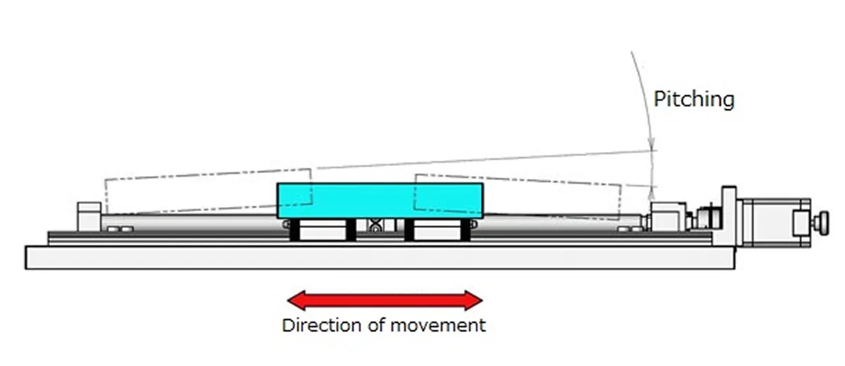
Pitching, yawing, rolling
What does "pitching, yawing, rolling" mean?
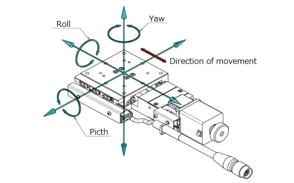
◆ Pitching: Rotating movement around the axis perpendicular (left and right) to the traveling direction (front and back)
→ Inclination of up and down
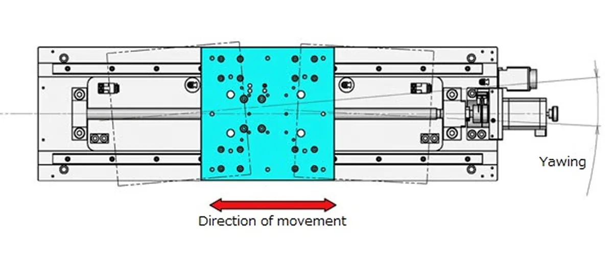
◆ Yawing: Rotating movement around the axis perpendicular (up and down) to the traveling direction (front and back)
→ Inclination of left and right
◆ Rolling: Rotating movement around the axis of travelling direction (forward and backward)
Straightness, pitching, yawing
Please tell me the difference between straightness, pitching and yawing
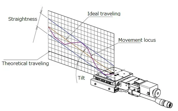
◆ Straightness [unit: μm]
・ Maximum displacement amount (distance) in the horizontal and vertical directions with respect to the ideal movement axis
◆ Pitching [unit: ″]
・ Maximum displacement angle in the vertical swing direction
◆ Yawing [unit: ″]
・ Maximum displacement angle in the horizontal swing direction
[Rotary stage] Difference between eccentricity and runout
Please tell me the difference between eccentricity and runout of rotary stage
◆ Eccentricity [unit: μm]]
・ Displacement of center axis of rotation in horizontal direction
◆ Runout [unit: μm]]
・ Maximum difference of displacement with respect to the reference plane when making one rotation with outer circumference as measurement point
Difference between parallelism and motion parallelism
Please tell me the difference between parallelism and motion parallelism
◆ Parallelism [unit: μm]
・ Fix the stage on the reference plane.
・ A numerical value indicating how parallel the stage carriage and the reference plane are.
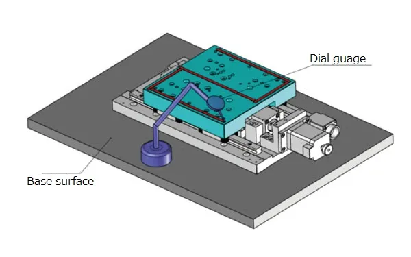
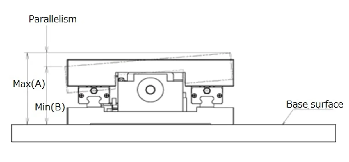
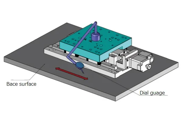
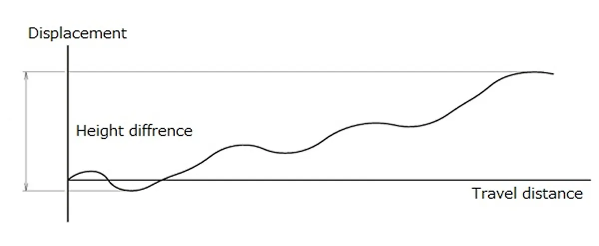
◆ Motion parallelism [unit: μm]
・ Fix the stage on the reference plane.
・ Place equipment for measuring the height with the reference plane on the stage carriage.
・ Maximum difference of measured values by moving the stage
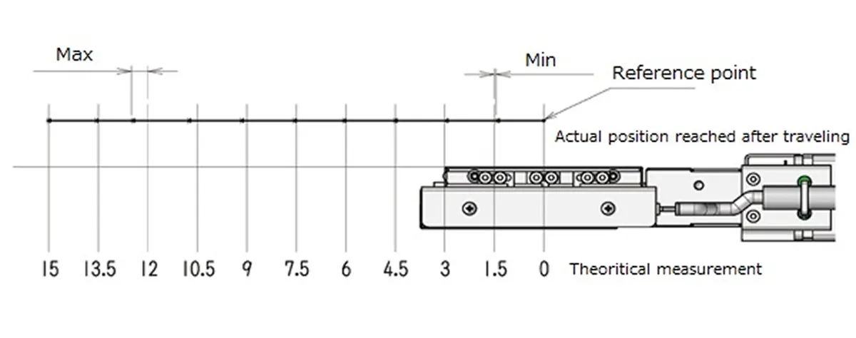
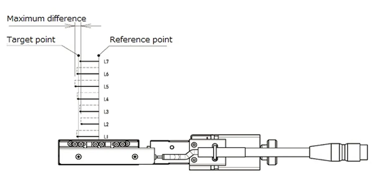
Uni-directional positioning accuracy, Repeatability positioning accuracy, Lost motion
Please tell me the difference among uni-directional positioning accuracy, repeatability positioning accuracy and lost motion
◆ Uni-directional positioning accuracy [unit: μm] A value representing "How much Point B has a possibility of positional deviation when X is moved from Point A to B?".
(Definition)
Send one-tenth of the total stroke, measure 10 points, and measure the maximum difference between measured values
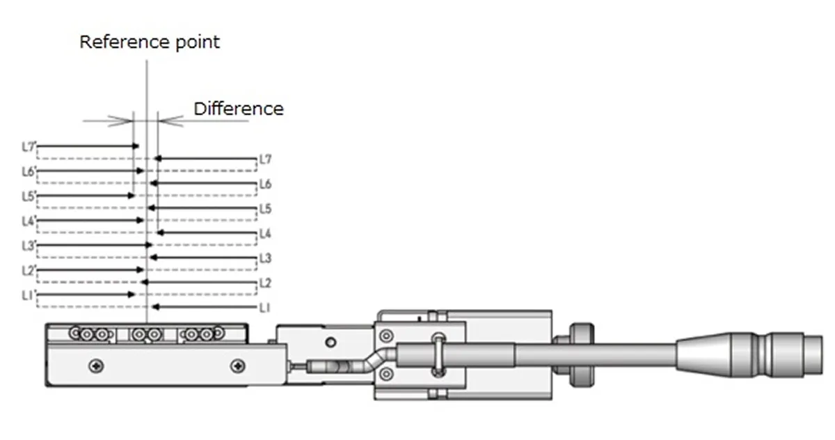
◆ Repeatability positioning accuracy [unit: ± μm]
A value representing "When you want to go back and forth the same place, what level of position shift will occur?"
(Definition)
Repeat the positioning seven times from the same direction for any one point to measure the deviation from the actual stop position.
Calcurate a half of the maximum difference of the measured deviation.
Biggest value among the three points of the center and both ends of the stroke.
◆ Lost motion [unit: μm]
A value representing "What range of deviation will occur when trying to stop at the same place on both back and forth directions?"
(Definition)
Make positioning toward arbitrary point (point A) from point B.
The actual stop position at this time is the point C.
(* Positioning from the Positive direction)
Move in the opposite direction of point B. --- Point D
····· Make positioning from point D to point A.
The actual stop position at this point is the point E
(* Positioning from the Negative direction)
Repeat this measurement seven times each in the positive and negative directions.
Calcurate the difference between “average of seven measurements at point C” and “average of seven measurements at point E”.
The largest value when this is done at the 3 points (center of the stroke and both ends).
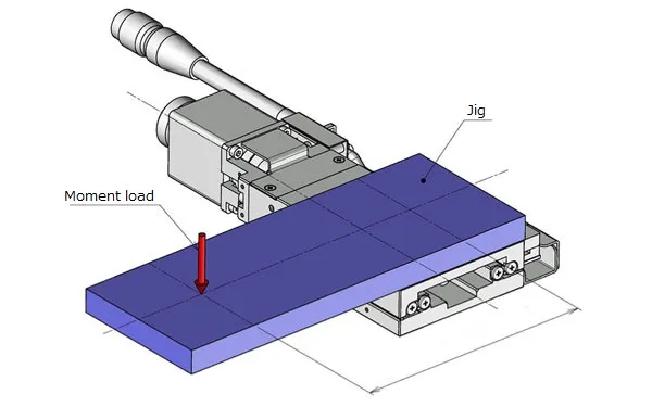
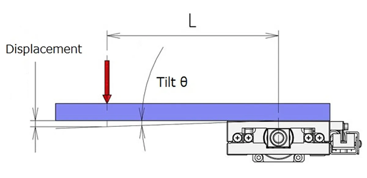
Moment rigidity
What is the moment rigidity?
◆ Moment rigidity [Unit: "/ N · cm]
・The displacement angle per 1 N · cm when moment load is applied toward the stage carriage in the direction of the respective pitch, yaw & roll
* Based on the distance from the center of the stage carriage (upper surface)
* The moment rigidity value in the catalog is described as a representative actual measurement value.

Resolution of servo motor option
We are considering the servo motor option of the KXL06 series (1 mm lead type).
What is the minimum resolution of this product?
The servo motor option (option code UA) uses Mitsubishi Electric AC servomotor (model: HG-KR053),
which is used a 22-bit encoder type and can be divided into 4194304 by one motor rotation (360 °).
*4194304 P/R
The stage moves 1 mm (1000 μm) with one rotation. Therefore, “1000 μm / 4194304 ≒ 0.0002384 μm” is the theoretical minimum resolution.
* It is different from actual following capability. It does not guarantee movement with the above resolution.
What is reverse type (R type)
What kind of direction is the difference of reverse type (R type)?
It is the direction which reflected the motorized stage in the mirror.
The cable connector and limit sensor position will be on the opposite side.
Acceleration and deceleration
How should we calculate acceleration?
Please also tell me the relationship with acceleration / deceleration time.
The acceleration is the rate of change of speed per unit time, and is expressed as “m / sec^2 (meters per secsec),“ etc.
If it comes to 10 mm / sec in 100 msec (= 0.1 seconds), the acceleration in this case is 10 mm / sec ÷ 100 msec (= 0.1 seconds) = 100 mm / sec^2 (0.1 m / sec^2)
* When the start pulse is 0 (zero)


